When a fault occurs, how can I quickly troubleshoot the problem of the self-healing low voltage shunt capacitor?
Release Time : 2025-05-22
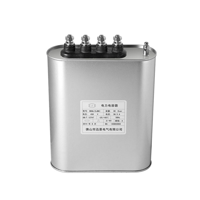
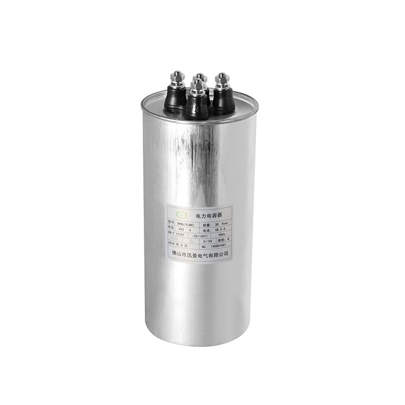
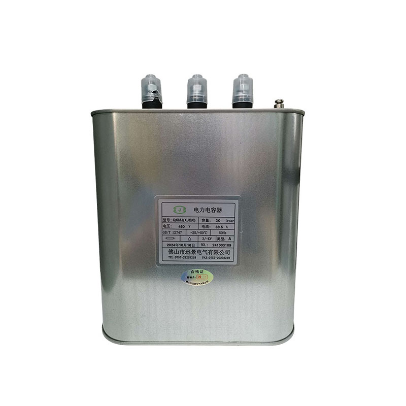
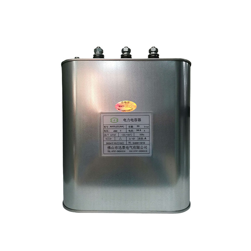
Self-healing low voltage shunt capacitor plays a key role in reactive power compensation in the power system. Once a fault occurs, it may cause the power factor to drop, the line loss to increase, and even cause the equipment to trip. Rapid troubleshooting requires combining equipment principles, operating parameters and on-site conditions, and following the principle of "first outside, then inside, first simple, then complex".
After the fault occurs, first visually check whether there are obvious abnormalities such as bulging, oil leakage, and burning of the terminal. If the shell is found to be swollen, it may be due to internal dielectric breakdown or excessive temperature causing gas production; oil leakage may indicate seal failure and need to be shut down immediately. At the same time, read the data of the intelligent monitoring device of the capacitor bank and record the current voltage, current, power factor, temperature and other parameters: if the current increases abnormally and the power factor drops sharply, it may be due to internal breakdown of the capacitor or failure of some components; if the temperature exceeds the upper limit specified by the manufacturer (such as 70℃), be alert to poor heat dissipation or increased dielectric loss. In addition, check the recent operation log to confirm whether there is an overvoltage shock (such as lightning strike, switch operation) or long-term overload operation before the fault, which provides clues for fault location.
The focus of the investigation turns to the external electrical connection system. First, check whether the protective devices such as fuses and circuit breakers are in operation: if the fuse melts, it is necessary to distinguish whether it is caused by overcurrent due to capacitor failure or short circuit in other parts of the line. Before replacing the fuse, use a multimeter to measure the insulation resistance of the two poles of the capacitor to the shell (normally it should be ≥2000MΩ). If the insulation resistance is lower than 500MΩ, it indicates that the internal insulation is damaged. Then check whether the terminal is loose or oxidized, and use a torque wrench to detect the tightening torque of the screws (usually 8-12N·m). Poor contact may cause local heating and burn the terminal. For a group cabinet with multiple capacitors in parallel, it is necessary to measure the current balance of each branch one by one. If the current deviation of a certain capacitor exceeds 10%, it may be that the capacitor capacity is attenuated or the internal contact is poor.
Use professional instruments to test electrical performance. The first step is to use a 2500V megohmmeter to measure the insulation resistance between the poles and the poles to the ground. If the resistance value drops by more than 30% compared with the factory value, it means that the medium is aging or damp. The second step is to use a capacitance bridge tester to measure the actual capacitance value of the capacitor and compare it with the rated value: if the capacitance value is greater than 110% of the rated value, it may be that the internal component breakdown causes the number of parallel connections to increase; if it is less than 90% of the rated value, it may be that the component is aged and broken or self-healing fails. For three-phase capacitors, the unbalance of the three-phase capacitance must also be measured. If it exceeds 5%, it is considered abnormal. During the test, it should be noted that after the capacitor is powered off, it must be fully discharged through the discharge resistor (discharge time ≥ 5 minutes) to avoid residual charge causing electric shock or damage to the instrument.
Abnormal temperature rise is a common precursor to capacitor failure. Use an infrared thermal imager to detect the surface temperature distribution of the self-healing low voltage shunt capacitor. Under normal circumstances, the temperature difference of each part should be ≤5℃. If the temperature of a certain area is significantly higher than that of other parts, it may be due to poor internal contact or concentrated dielectric loss. At the same time, the harmonic content of the system is detected by the power quality analyzer. When the harmonic number exceeds 5 and the amplitude exceeds 5% of the nominal voltage, it will cause the capacitor to over-current and heat, accelerating insulation aging. If the harmonics are found to be excessive, it is necessary to further check the nonlinear load (such as inverter, rectifier), and consider installing a harmonic filter at the front end of the capacitor bank to avoid recurrence of the fault.
The core advantage of the self-healing low voltage shunt capacitor is that the dielectric can automatically restore insulation after breakdown. For capacitors suspected of self-healing failure, an offline self-healing function test can be performed: first apply 1.3 times the rated voltage for 1 minute, and then reduce it to the rated voltage to observe whether it can operate stably. If it breaks down again or an abnormal sound occurs, it means that the self-healing mechanism has failed and needs to be disassembled for inspection. Disassembly must be carried out in a safe area. After ensuring that the capacitor is fully discharged, open the shell and observe whether the metallized film has large-area carbonization marks. Normal self-healing points should show white spots with a diameter of ≤2mm. If the carbonization area exceeds 5% of the film area, the component needs to be replaced as a whole.
Deterioration of environmental conditions may indirectly lead to capacitor failure. Check the ventilation and heat dissipation of the installation environment. If the cabinet air inlet is blocked or the fan is damaged, it will cause internal temperature accumulation; for places with a lot of dust, it is necessary to clean the dust on the surface of the capacitor and the heat dissipation ribs to avoid affecting heat dissipation. At the same time, check whether the capacitor mounting bracket is loose and whether there is a vibration source in the cabinet (such as the operation of a nearby motor). Long-term vibration may cause the internal component solder joints to fall off or the lead wires to break. For capacitors installed outdoors, check whether the protective shell is rusted and whether the sealing strip is aging to prevent rainwater from seeping in and causing a short circuit.
If the fault phenomenon is atypical or intermittent, it can be reproduced by simulating operating conditions. For example, gradually increase the load to observe the change in capacitor current, or monitor the response of the capacitor when the system voltage fluctuates. For capacitor groups that have repeatedly experienced the same type of fault, it is necessary to analyze whether there are design defects (such as unreasonable capacity configuration and improper switching strategy), which can be improved by adjusting the capacitor grouping and optimizing the parameters of the automatic switching device. In addition, establish a preventive maintenance plan: perform infrared temperature measurement and wiring tightening once a quarter, perform insulation resistance and capacitance value tests once a year, record data and draw trend curves, identify capacitors with degraded performance in advance, and avoid sudden faults affecting power supply reliability.
Through the above systematic troubleshooting process, the fault point of the self-healing low voltage shunt capacitor can be located in the shortest time, and repair or replacement can be decided according to the degree of damage. It is worth noting that capacitors are high-voltage energy storage devices. All detection operations must be performed by certified electricians, and safety regulations such as power outages, electrical testing, and discharge must be strictly observed to ensure that the troubleshooting process is safe and controllable.


